Whitepapers
The joint information below helps define and clarify the tooling and fixture options for a new welding project.
(We have found these visualizations help when defining a new job.)
Basic Square Groove Welds
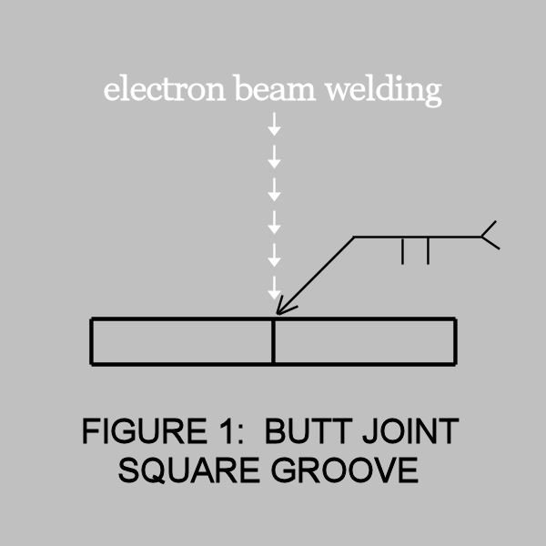
Square Groove — Figure 1
The square groove butt joint, illustrated in Figure 1, is a basic joint design for electron beam welding. Generally, it is the most practical and most efficient configuration to use.
The use of this design assumes accessibility to both surfaces for machining and inspection purposes. This joint design may be used for materials as thin as 0.005″ or as thick as 2″ or more.
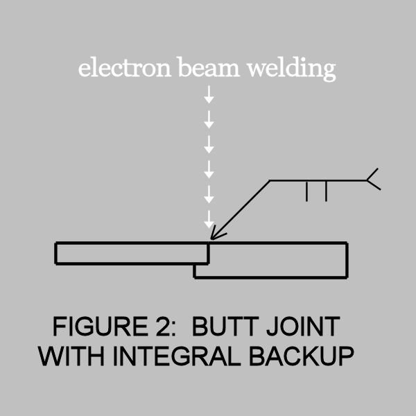
Integral Backup — Figure 2
The butt joint configuration illustrated in Figure 2 is sometimes called a butt-lap joint and is used to provide alignment and filler material.
The alignment feature can simplify tooling requirements, prevent mismatch in linear welds, and is useful as a self-centering device in its cylindrical parts.
Although the additional material is located on the root surface, it will provide a positive top bead reinforcement. It can provide material to stop the beam within the thicker member to prevent weld metal spatter associated with full penetration weldments.
It can also be used to an advantage with alloys, such as aluminum, and solving weld root porosity problems.
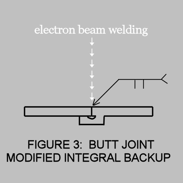
Modified Integral Backup — Figure 3
The modification to the integral backup in Figure 3 is sometimes used for crack sensitive materials.
This joint preparation can be expensive, but is used in fatigue-critical applications where the notch effect of non-fused material and a change in cross-section is minimized.
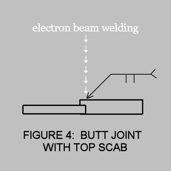
Top Scab — Figure 4
The configuration in Figure 4 is useful when the face surface of the weldments is critical or where undercut or under fill is apt to be a problem.
Titanium and magnesium alloys are materials that often require this approach to providing adequate filler material.
A scribe line is used for weld joint alignment and weld tracking.
Angular Beam — Figure 5
The technique shown in Figure 5 is used when mating parts vary in thickness, scarfing of the thicker member is undesirable, and welding from the opposite side is not feasible.
It is essential to widen the beam to ensure a fusion of both abutting surfaces of the weld joint.
The angle should be only as large as necessary to assure no scarfing, but not so large as to exaggerate the tendency to produce a lack of root fusion. This is not usually a problem with joint thicknesses up to 0.375 inches.
Thicker joints may require an angle cut on the joint preparation to prevent the missed joint type, lack of fusion defect.
Tube Welds
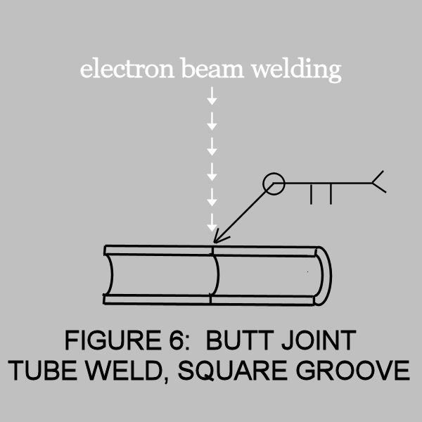
Tube Welds — Figure 6
The most direct approach to welding tubular sections is illustrated in Figure 6.
Fit-up is critical, and fixturing is important to avoid misalignment and concentricity problems.
A lower power tacking pass with the electron beam helps to maintain alignment prior to a full penetration pass.
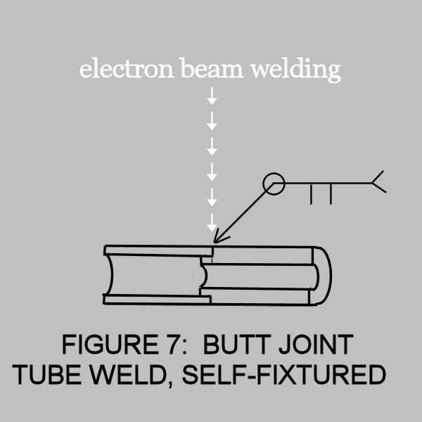
Tube Weld, Self-Fixtured Joint — Figure 7 & 8
When joint alignment is critical, the design in Figure 7 provides concentricity without the need for elaborate tooling.
A tight slip fit to an interference fit is recommended for proper welding.
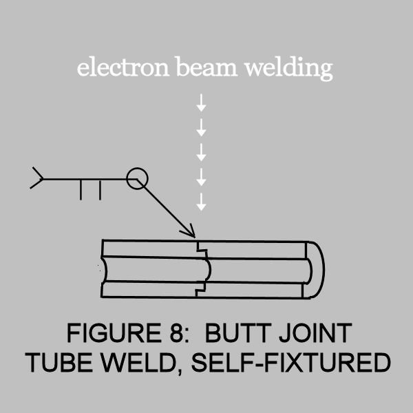
Tube Weld, Self-Fixtured Joint — Figure 7 & 8
Figure 8 illustrates another variation of the self-fixtured joint that has the feature of a smooth bore for fluid systems that cannot tolerate flow restrictions.
The step typically is on the order of 0.010”.
The step must be consumed by the narrow electron beam, therefore any steps much greater than 0.010” will require larger than desired beam diameters and can risk “missed joint” type lack of fusion defects. Scribe lines are used to locate the internal weld joint.
Solid Bar Welds
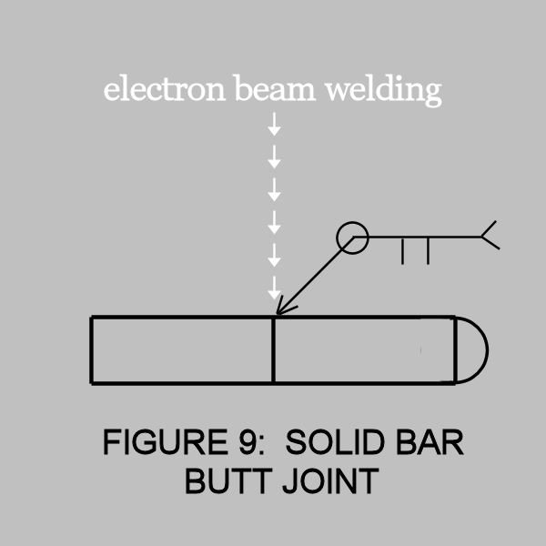
Solid Bar Butt Joint — Figure 9
The simple square groove butt joint for the solid round bar in Figure 9 can be adequate for many applications; however, misalignment can be a problem.
This design will require the use of tack welding.
Partial penetration to the midpoint results in zero welding speed at the center and a possible porosity problem. It is better to attain 60-70% penetration to minimize porosity formation.
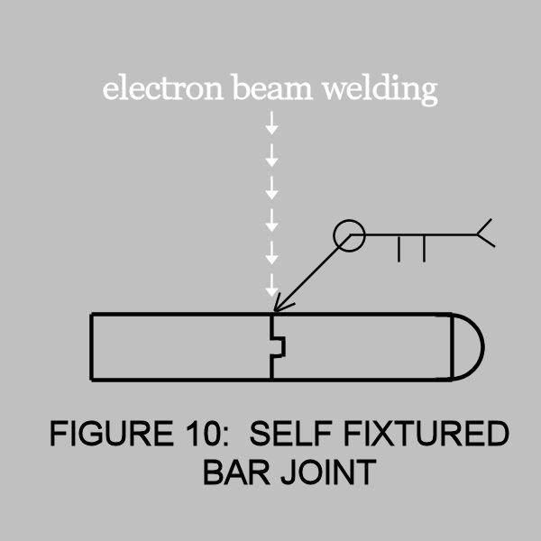
Self-Fixtured Bar Joint — Figure 10
When alignment is critical, the self-fixtured butt joint in Figure 10 eliminates the need for elaborate tooling and extensive tack welding.
Usually 0.010″ to 0.020″ engagement is sufficient to provide proper alignment.
If the configuration includes a hollow area, such as the center tap, there will be a problem with trapped air, especially when tight or press fit joint is used. The trapped air can cause porosity and expulsion of molten metal at the tie-in after a 360° weld.
Whenever possible, hollow areas should be vented to the outer surface of the part. This can be accomplished by scoring the joint faying plane with a scribe line(s) 0.001″ to 0.003″ deep.
Plug Welds
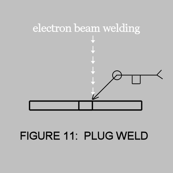
Plug Weld — Figure 11
The simple plug weld in Figure 11 works well with most materials provided the fit-up is tight, with an interference fit being preferred.
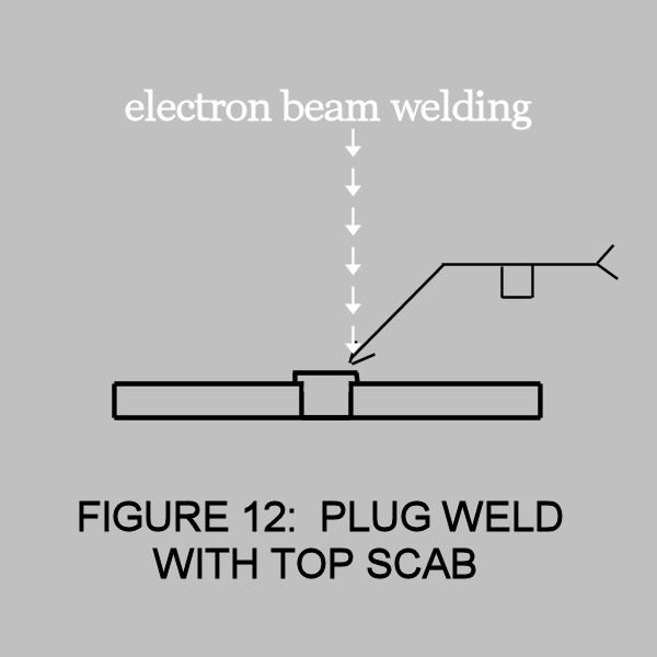
Plug Weld with Top Scab — Figure 12
With materials such as titanium and magnesium, undercutting can become a problem. In these cases, a plug with a “top scab”, as depicted in Figure 12, is recommended.
When welding this type of “scab” joint, as in any blind weld, the use of scribe lines is recommended to aid in the optical tracking of the joint.
“T” Joint Welds
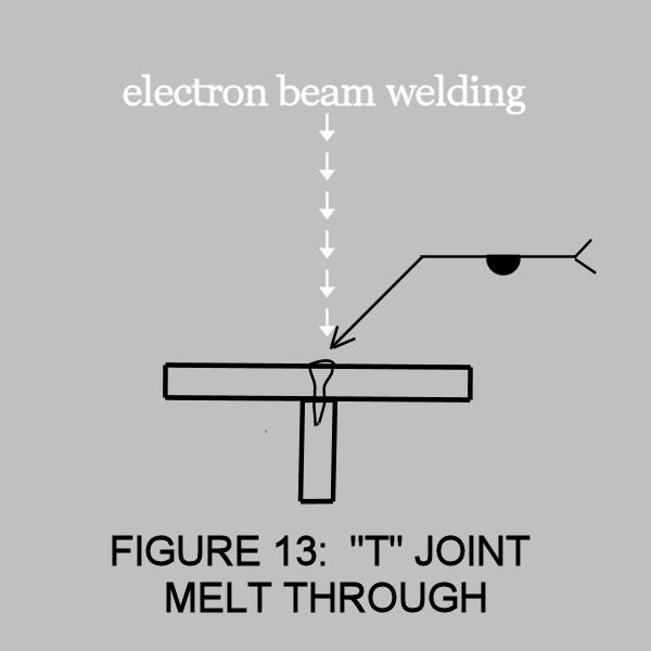
“T” Joint Melt Through — Figure 13
The melt-through or blind tee joint in Figure 13 is used when a part configuration prevents access the faying plane.
Examples of this condition are reinforcing rings inside a cylinder, plate-fin heat exchangers, or integral stiffened sheets.
Part and scribe line locations are critical to the success of welding this joint design.
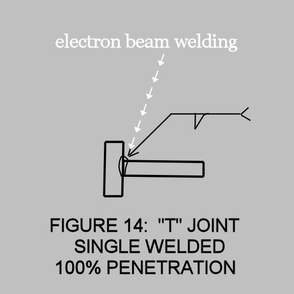
Single Weld “T” Joint — Figure 14
Full penetration “T” joints may be welded from one side using the electron beam welding process in Figure 14.
The beam is introduced to the joint at a slight angle and can produce a “double fillet” effect on thin materials.
Edge Joint & Tier Welds
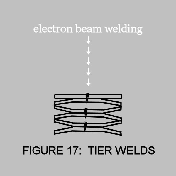
Tier Joint — Figure 17
Components containing several stacked weld joints, usually lap joints, can be simultaneously welded as in any “tier”.
This is unique to the electron beam welding process, using the keyhole welding mode.
This joint design may be limited by access to NDT techniques.


Edge Joint Ex 1 & Ex 2 — Figure 16a & 16b
Edge joints are generally used with sheet materials such as hermetically sealed cans, etc. This type of joint is especially useful in areas where the parts are used, disassembled, refurbished, and resealed by welding.
Figure 16a and Figure 16b show two types of edge joints.
This weld requires a low power, defocused electron beam. High welding speeds are possible.
Metal to metal contact provided by good quality copper chill bars is essential to control weld puddle contour.
Lap & Fillet Welds
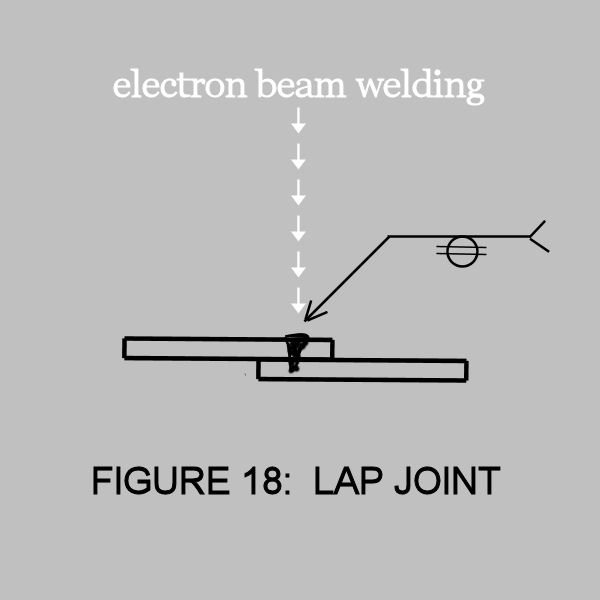
Lap Joint — Figure 18
The lap joint configuration in Figure 18 is fairly common in use, especially in sheet-metal thicknesses.
In very thin gauges (0.005″), this type of joint is sometimes more expedient to use, by virtue of simpler fixturing, than a square groove butt joint. Again, the weld interface width determines the joint strength, therefore a defocused beam having a larger weld width will have an increased strength.
The joint can be spot welded or seam welded.
In some cases, sinusoidal beam deflection transverse to the direction of weld travel is employed as a means to provide greater weld interface per unit length.


Fillet Weld – Ex 1 & Ex 2 — Figure 19a & 19b
The fillet weld joint design is generally useful in thicknesses up to 0.062″ where a full fillet is required. For thicknesses greater than 0.062″, electron beam welding may be useful if a less than full fillet is acceptable.
By defocusing the beam, the fillet weld may be enlarged and will present a smoother surface.
Filler wire is sometimes used to increase the fillet size.
As shown in Figure 19a and Figure 19b, the unique capability of the electron beam welding process can produce a fillet weld having a large depth to width ratio, resulting in a superior strength joint.
Miscellaneous Notes
Penetration Welds — Figure 22
A penetration weld is a trial and requires no joint preparation.
A penetration weld is the commonly used trial weld technique to determine the welding parameters for a specific part thickness.
Generally, it simulates conditions of an actual butt joint properly prepared and fixtured.
Note: Often known as bead-on-plate (BOP) weld.

Tack Welding — Figure 20
Tack welding with the electron beam is generally useful as a fixturing aid.
Tack welds are made at less than the power needed for full penetration (20% to 40%). It is often used in unrestrained parts to prevent opening-up of the seam as full penetration welding progresses.
The tack weld is also helpful in maintaining the concentricity of mating parts in rotary welds, although an interference fit is preferred.
Tacking can be made as intermittent welds, but 100% tacking is more desirable. Note, there is a difficulty in relocating the weld joint for the full penetration weld if 100% tacking is used, so an occasional interruption is preferred as an aid in centerline joint location.

Puddle Welding — Figure 21
Puddle welding is frequently used with locally preplaced filler metal additions.
Puddle welding is accomplished by manual manipulation of the workpiece under the beam, at low power, to locally fuse surface defects in materials or welds.
Also, puddle welding is frequently used with locally-preplaced filler metal additions.